EN

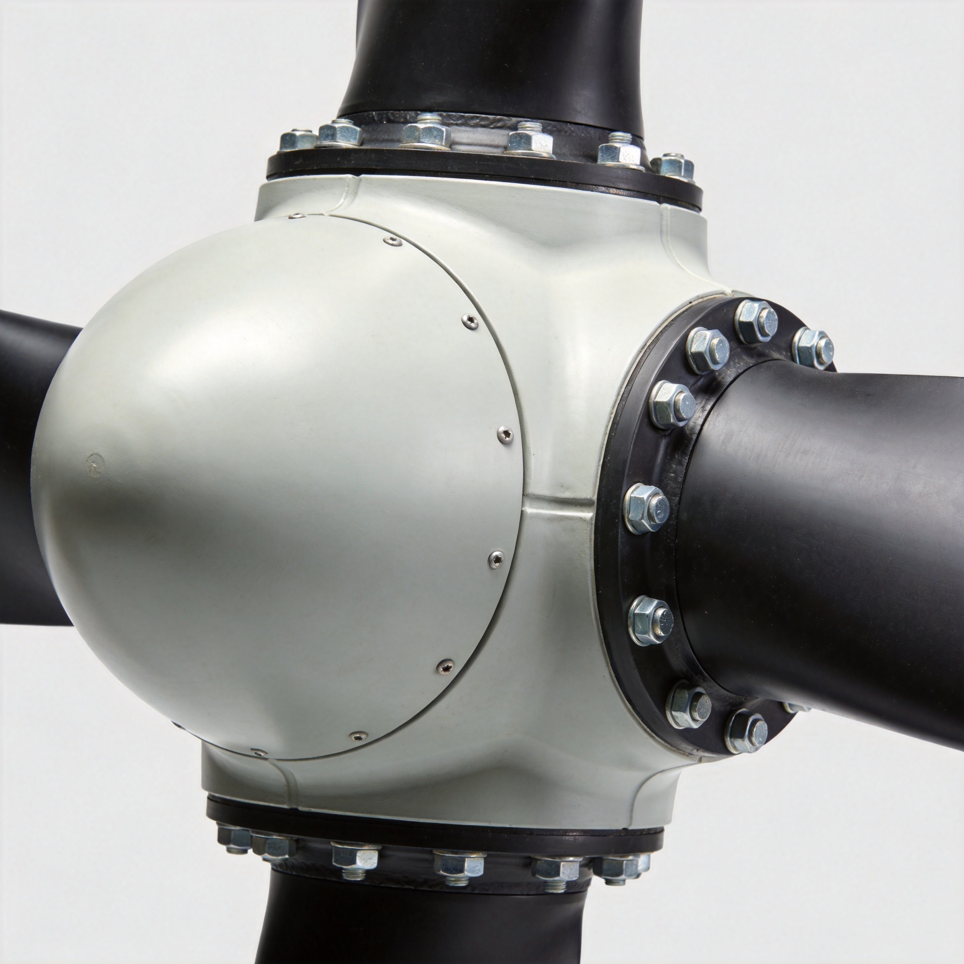
How to Address Fastener Fatigue in Wind Turbine Rotor Assemblies
Fastener fatigue in a wind turbine rotor assembly is rarely a single-part problem. A fastener works inside a clamped system that includes the joint faces, the mating components, the installation method, and a changing load path. When that system loses clamp force or transfers more alternating load into the fastener than intended, small damage can progress between planned service visits.
As a fastener selection engineer, I would start with the operating evidence rather than assume that a higher strength grade is the answer. Rotor assemblies see cyclic loading, vibration, temperature changes, and occasional load redistribution. The useful question is: what changed in the joint condition, and how has that change affected the fastener load cycle?
Why rotor-assembly fastener fatigue develops
A correctly assembled fastener is preloaded so that the clamped parts remain compressed through much of the service cycle. If preload falls, the joint can slip or open locally, and the fastener may carry a larger fluctuating share of the applied load. Research on eccentrically loaded wind-turbine bolts has linked reduced preload with larger stress-fluctuation ranges and higher fatigue demand. That does not make every low reading a failure diagnosis, but it does make preload loss an engineering concern.
In rotor work, bending is as important as direct tension. Misalignment, uneven bearing faces, local distortion, damaged threads, or a changed load path can bend a fastener while it is also being tensioned. Blade rotation turns these effects into repeated cycles. A threaded fastener that looks intact at a quick glance can therefore have a fatigue problem developing below a head, at the first engaged thread, or where it bears against an imperfect surface.
It is tempting to respond by specifying the highest-strength mechanical fastener available. That can miss the cause. If the actual issue is fit-up, torque scatter, lubrication changes, or a relaxed joint face, changing only the fastener grade may leave the damaging load path in place.
Start with a structured condition review
Before replacing a fastener, separate observable symptoms from conclusions. Review the OEM service instructions, the assembly record, prior retorque or tensioning work, vibration events, and any parts replaced near the joint. Compare the suspect location with adjacent locations instead of judging it in isolation.
- Look for joint movement: fretting debris, shifted witness marks, polished contact areas, or changes at the contact surface can indicate loss of clamp action.
- Check the installation history: verify the specified tightening method, sequence, tooling condition, and whether the documented procedure was followed.
- Inspect the load path: identify damaged bearing faces, gaps, misalignment, corrosion products, or a mating part that may have altered how the fastener is loaded.
- Record evidence by location: map each fastener position, observed condition, and measurement result so that a local pattern is visible.
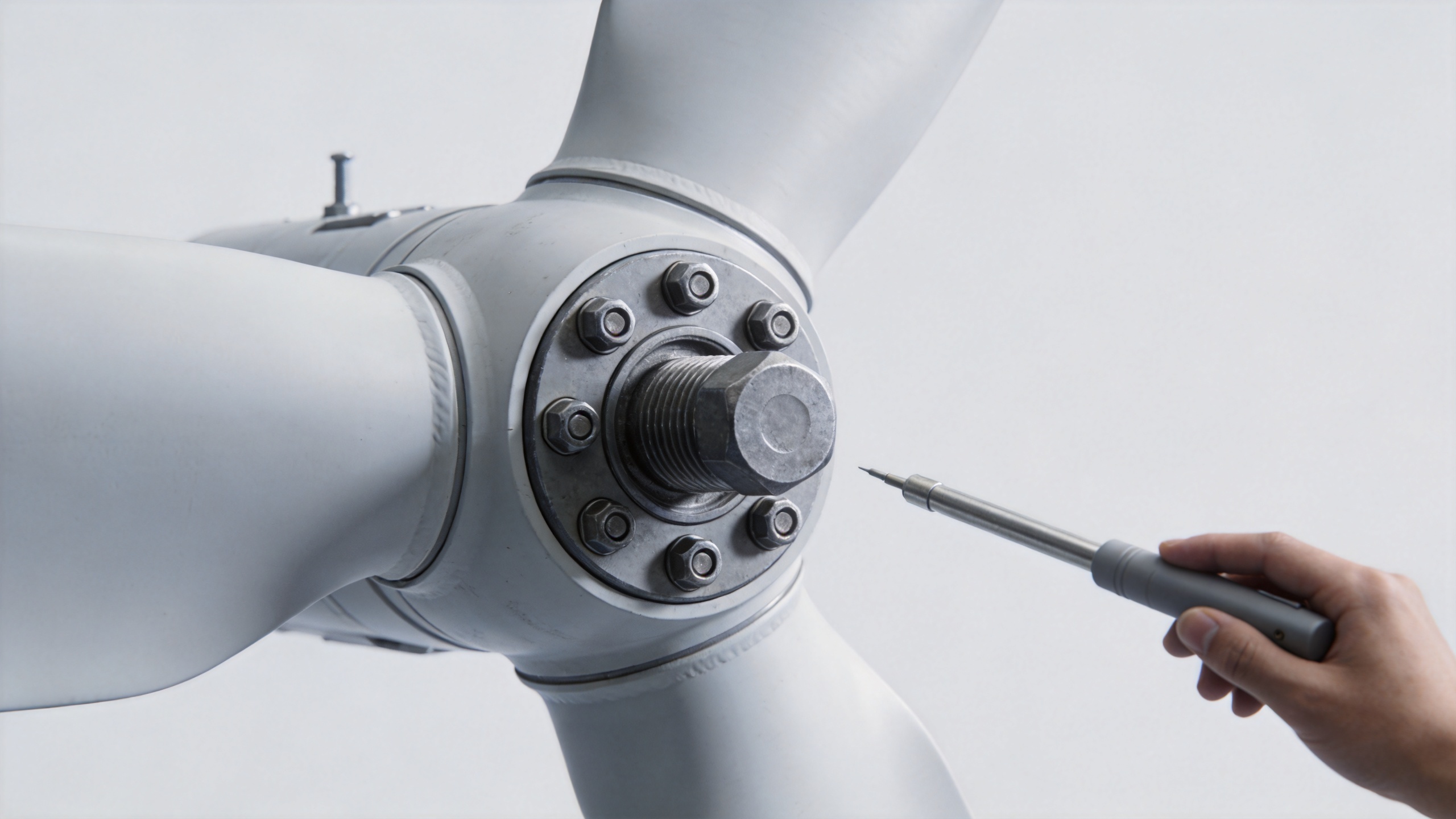
A stainless fastener may need special attention where its corrosion resistance is useful but the mating materials, coatings, or assembly compound create friction uncertainty. Material choice belongs in the review, but it should not replace a check of actual clamp condition and geometry.
Do not treat torque as a direct preload measurement
Torque can be useful for screening when the approved maintenance procedure calls for it, yet torque is affected by friction in threads and under the bearing surface. It does not automatically reveal the installed tension in a fastener. In a critical rotor joint, decide with the responsible engineer whether the situation needs a method that verifies elongation, tension, or another approved preload indicator.
This distinction matters after maintenance. A fastener may turn at a given torque because of surface condition or lubricant variation, while another fastener may appear stable even though the clamped stack has changed. Treat torque results as one piece of evidence, then compare them with installation records, joint condition, and the inspection plan.
Choose an inspection path that fits the suspected mechanism
Visual inspection is a starting point, not a fatigue clearance. For accessible areas, examine heads, washers, exposed shanks, thread runouts, and surrounding joint faces under suitable lighting and cleaning controls. If there is a crack indication, local corrosion, deformation, or repeated preload loss, escalate according to the OEM process and site engineering authority.
Non-destructive methods may be appropriate when the risk justifies them. Published wind-turbine work has explored phased-array ultrasonic testing for bolted connections. The applicable method, acceptance criteria, technician qualification, and access constraints must be set by the equipment owner or qualified engineering team. The goal is not to use advanced inspection everywhere; it is to match the method to a credible fatigue mechanism.
Correct the joint, not just the individual fastener
When replacement is required, control the whole assembly sequence. Confirm the correct fastener specification, lot traceability requirements, mating hardware, surface condition, lubrication status, and tightening sequence before installation. A custom fastener should only be introduced when its dimensions, material, thread form, coating, and validation route are approved for the joint; custom geometry alone is not a fatigue remedy.
Also inspect the removed fastener carefully within the site’s failure-analysis process. Fracture location, thread damage, corrosion pattern, and bearing-face marks can help distinguish overload, bending, inadequate clamp force, or installation damage. Preserve evidence when an engineering review is likely, rather than discarding the part during routine replacement.
Build a practical follow-up plan
A useful follow-up plan names the locations to revisit, the measurement or inspection method, the acceptance authority, and the service conditions that trigger escalation. For a rotor assembly with repeated findings, include adjacent fastener locations and mating components; a single replacement can hide a broader joint issue.
- Document the initial condition and any replaced fastener locations.
- Restore the joint using the approved components, procedure, and calibrated tooling.
- Verify the condition with the method specified for that connection rather than relying on a generic check.
- Review early follow-up evidence for patterns in preload loss, movement, or surface damage.
- Escalate recurring findings to the turbine OEM or qualified structural engineer for load-path and repair assessment.
Fastener fatigue in wind turbine rotor assemblies is manageable when maintenance teams connect inspection evidence to the physics of the clamped joint. The priority is not simply to tighten a fastener harder. It is to restore the specified joint condition, verify it with an appropriate method, and investigate any repeated sign that the fastener is carrying an unfavorable cyclic load.