EN

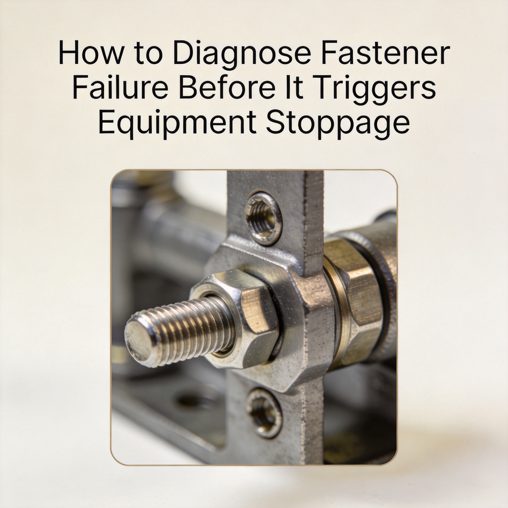
How to Diagnose Fastener Failure Before It Triggers Equipment Stoppage
A fastener rarely becomes a maintenance issue at the exact moment it breaks. More often, the joint gives small, observable signals first: a changed witness mark, rust at a bearing surface, fretting dust, a gap that was not present during the last round, or a torque result that no longer agrees with the approved assembly record. Treating those signals as an inspection trigger can turn an unplanned equipment stoppage into scheduled corrective work.
From a fastener selection engineer’s perspective, the useful question is not simply “Is this bolt damaged?” It is whether the joint is still carrying load as intended, whether its clamp condition has changed, and whether returning the equipment to service would add risk. The diagnostic path below helps maintenance teams move from visible evidence to a controlled decision.
Start with the joint, not the loose hardware
A fastener works as part of a joint system: mating materials, hole condition, washers, locking features, surface finish, applied load, temperature, vibration, and installation method all affect the result. A threaded fastener can look intact while the clamped parts have settled, the joint has slipped, or preload has reduced. Conversely, a mark on the head may be cosmetic rather than evidence of a structural problem.
Before touching the hardware, record the equipment location, joint function, operating condition, and the approved specification if it is available. Note whether the joint is safety-critical, load-bearing, pressure-containing, guarded, or near a rotating component. Then compare it with a known-good location where the duty and assembly are the same. That comparison often reveals a changed gap, a rotated nut, or a displaced washer more quickly than an isolated visual check.
Use a three-pass inspection routine
Pass 1: Look for movement and loss of clamp
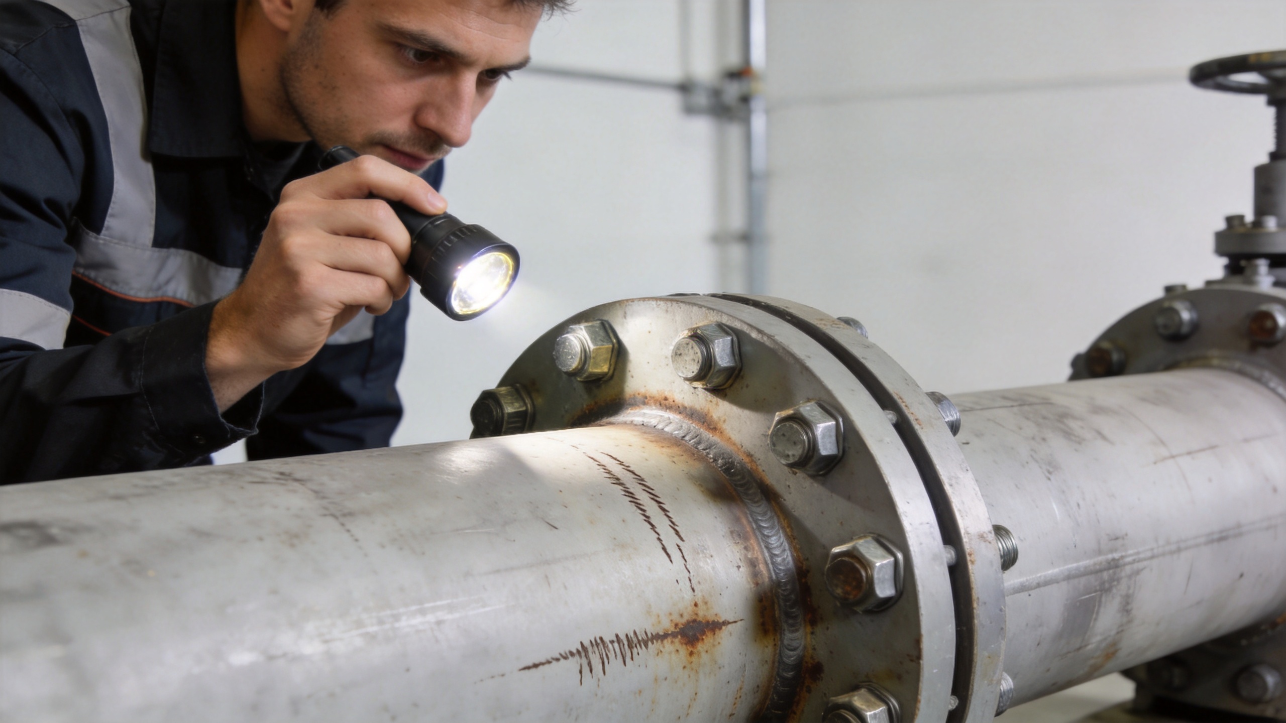
Begin with evidence that the joint has moved. Misaligned torque-stripe or witness marks, polished contact faces, reddish-brown or dark fretting debris, ovalized holes, and a washer that has walked from its original seat all deserve attention. On painted assemblies, a cracked paint ring around a head or nut can be a useful clue, but it is only a clue; verify it against the joint geometry and maintenance history.
Do not tighten the fastener immediately just because a mark has shifted. First document the condition and identify the specified verification method. Torque is an indirect indicator of clamp condition, and adding torque without understanding the cause can hide a problem such as embedment, joint slip, damaged threads, or an incorrect stack-up.
Pass 2: Inspect corrosion, heat, and surface distress
Corrosion is more than an appearance issue when it affects bearing surfaces, threads, or the shank. Look closely where water can remain: under heads and washers, at thread runout, around flanges, and in crevices between dissimilar metals. White deposits on coated hardware, rust bleed from a joint line, pitting, plating lift, or seized threads can change friction and reduce the consistency of a later torque check.
Also look for heat discoloration, softened nonmetallic locking elements, damaged coatings, or residue from lubricants and process fluids. A stainless fastener used in a wet or chemically active environment still requires a compatibility review with the mating material and service fluid. Color alone does not establish the failure mode, so pair the observation with the equipment’s temperature, washdown, and exposure history.
Pass 3: Check for deformation and fatigue indicators
Inspect the shank, head-to-shank transition, first engaged threads, and the thread runout. Necking, bent hardware, rounded drive features, damaged threads, or a nut that runs unusually freely can indicate overload, installation damage, or repeated movement. When a fracture has already occurred, a relatively flat surface with little necking may be consistent with fatigue, but a qualified failure analysis is needed before assigning a root cause.
Thread roots deserve particular attention in cyclic service. Technical failure investigations have documented fatigue cracking beginning at thread roots where corrosion, oscillation, and inadequate preload combined. That does not mean every corroded joint is about to fracture; it means the inspection should consider the combined condition rather than treating rust, vibration, and torque loss as separate issues.
Match the symptom to the next action
| What you observe | What it may indicate | Controlled next action |
|---|---|---|
| Witness marks no longer align | Relative rotation or joint settling | Document the shift; compare with a like-for-like joint; verify using the approved procedure. |
| Fretting debris or polished contact faces | Micro-movement at the contact boundary | Check load path, hole condition, clamp surfaces, and vibration exposure before retightening. |
| Rust bleed, pitting, or coating loss | Environmental attack or trapped moisture | Assess material compatibility, protective finish, and whether threads or bearing surfaces need replacement. |
| Damaged threads or rounded drive features | Over-torque, cross-threading, or unsuitable installation tooling | Remove from service when permitted; inspect mating threads and installation controls. |
| Crack, bent shank, or visible stretch | Overload or fatigue-related damage | Escalate the joint; avoid reuse and review the load case before replacement. |
Verify without creating a second problem
Verification needs an approved work instruction. For some joints, that may involve a torque audit performed under defined conditions; for others, it may require elongation measurement, ultrasonic methods, direct-tension indicators, or a controlled removal-and-replacement process. The right method depends on the joint design and safety classification. A mechanical fastener in a lightly loaded enclosure does not demand the same escalation path as one in a drive train, pressure boundary, or structural frame.
Keep the inspection record practical: component ID, location, symptom, photos where allowed, witness-mark status, environmental evidence, verification result, corrective action, and the reason for any replacement. This creates a trend line. If several joints on the same asset show the same pattern, the cause may lie in vibration, thermal cycling, access constraints, tooling calibration, or a specification mismatch rather than in one isolated fastener.
When replacement is the safer decision
Replace rather than reuse hardware when it is cracked, visibly stretched, thread-damaged, heavily corroded at critical surfaces, or removed from an application whose procedure requires new hardware. Use the approved grade, dimensions, finish, locking approach, and lubrication condition. A custom fastener should be checked against the drawing revision and applicable tolerances before it is introduced into a repair; a dimensional mismatch can create an assembly issue even when the nominal designation appears similar.
There is also a planning tradeoff. Holding large quantities of every repair item can lower unit cost, but it may increase exposure to obsolete specifications or mixed batches. For equipment with changing designs, controlled smaller replenishments and traceable lots can be more useful than a large inventory that no longer matches the current drawing.
A short field checklist for each suspect fastener
Use the same questions for every suspect fastener so that an inspection route produces comparable records. Is the fastener identified by location and drawing reference? Has this fastener moved relative to its witness mark? Does the fastener show corrosion at a load-bearing surface, damage at the threads, or evidence of rubbing? Is the fastener in a vibration, thermal-cycle, or wet-service zone that changes the review interval?
For a threaded fastener, check both the visible thread condition and the first engaged threads, then compare the approved installation condition with the current joint. Record whether the threaded fastener can be verified under the specified method rather than improvising a torque value. Where a mechanical fastener connects different materials, examine the washer, hole edge, and clamped surfaces as part of the same finding. A mechanical fastener is only as reliable as the joint stack it is holding.
For each stainless fastener, note the environment and the adjacent material before deciding that discoloration is harmless. A stainless fastener should be evaluated for service compatibility, not merely for appearance. If a custom fastener is specified, verify revision, dimensions, and traceability before replacement. Do the same for any custom fastener that differs from standard stock. This disciplined sequence keeps the fastener, the joint, and the maintenance decision connected.
Build early warning into routine maintenance
The most effective diagnostic program does not wait for a fastener to fail. Add critical joints to route-based inspections, define what “normal” looks like with photos or witness marks, and schedule a review after events that change loading: an impact, process upset, overhaul, temperature excursion, or repeated vibration alarm. During commissioning and after major maintenance, capture the baseline condition so later changes are easier to identify.
In practice, a fastener inspection is not a head-count exercise. It is a joint-condition review. First confirm the load and service environment, then inspect for movement, corrosion, and deformation, and finally verify the finding with the approved method. That sequence gives a maintenance team a clear basis to monitor, repair, or escalate before an equipment stoppage becomes the first warning.