EN

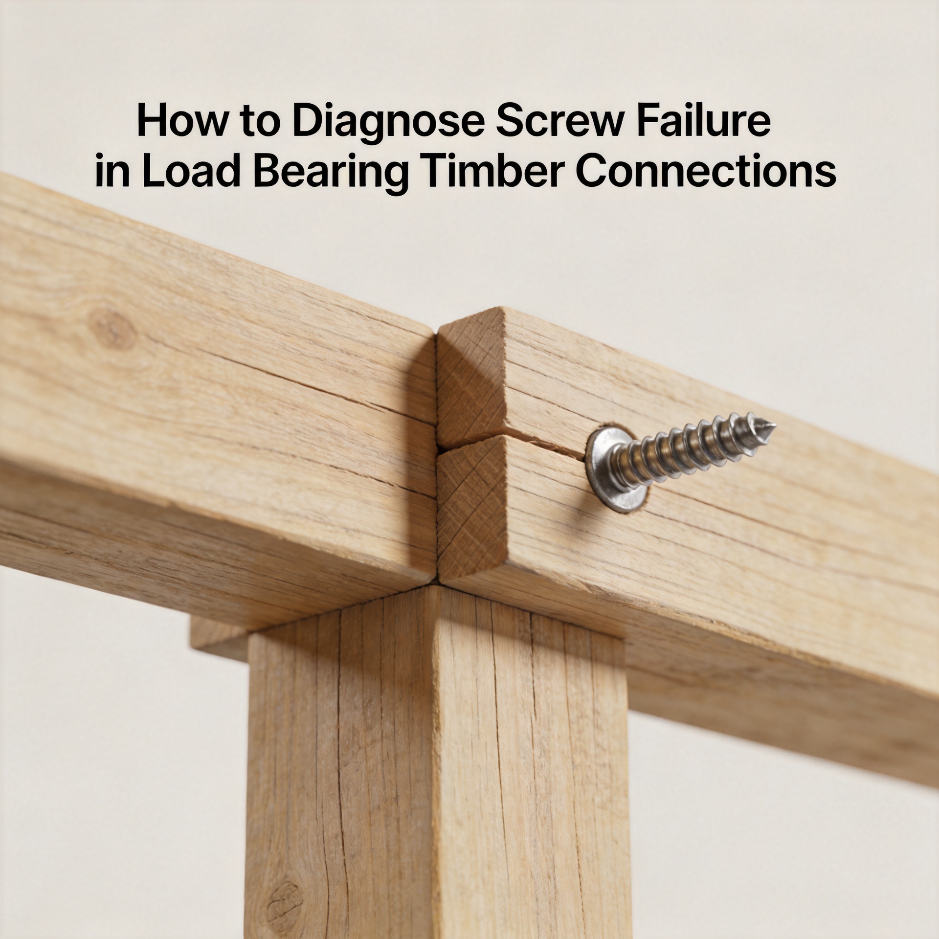
How to Diagnose Screw Failure in Load Bearing Timber Connections
A failed screw in a load-bearing timber connection calls for a safety and design review, not a quick replacement. Before loading the connection again, isolate the affected area where practical and have the repair approach reviewed by the responsible structural professional. A visible loose screw may be the last sign of a deeper issue: altered load path, wet timber, insufficient penetration, an unsuitable fastener, or installation damage.
As a fastener evaluator, I start with the evidence around the connection rather than the broken screw alone. Note where the member moved, which face opened, whether timber fibres are crushed or split, and whether several fasteners show the same symptom. This sequence helps separate a local installation problem from a connection that needs engineering reassessment.
Start with safety, records, and a clear failure map
Do not tighten, remove, or substitute every screw before documenting the condition. Photograph both timber members, the fastener head, the shank, surrounding checks, moisture staining, and any steel plate or washer. Mark the affected locations and record the member sizes, visible grain direction, connection angle, and recent changes in loading or moisture exposure.
Then collect the original drawings, calculation notes, product data, installation instructions, and batch traceability where available. For structural timber work, documentation matters: EN 14592 covers requirements for dowel-type fasteners including screws used in timber structures, but a marking or a general product label is not a substitute for the connection-specific design data. The installed screw must match the approved type, diameter, length, material, coating, and intended load direction.
Identify the failure mode before choosing a repair
Withdrawal or pull-out
Withdrawal occurs when a screw moves outward along its axis. Look for an enlarged entry hole, polished thread tracks, lifted heads, and a gap opening between members. Common contributors include insufficient threaded penetration in the receiving member, low-density or deteriorated timber, loading near end grain, repeated movement, or a changed moisture condition. Withdrawal performance depends on the actual timber, grain direction, effective thread engagement, and the approved design method; it should not be judged from length alone.
Head pull-through or local timber crushing
When the head pulls into the timber, the screw may remain intact while the wood beneath its head is crushed, torn, or split. Head pull-through is a recognized mode for load-bearing timber screws. Inspect whether the head or washer was specified for the connection, seated squarely, and supported by sound wood. A small head, a damaged seating face, or overdriving can reduce the bearing area and concentrate stress. Replacing the screw with a larger diameter without checking spacing and edge distances can create a new splitting risk.
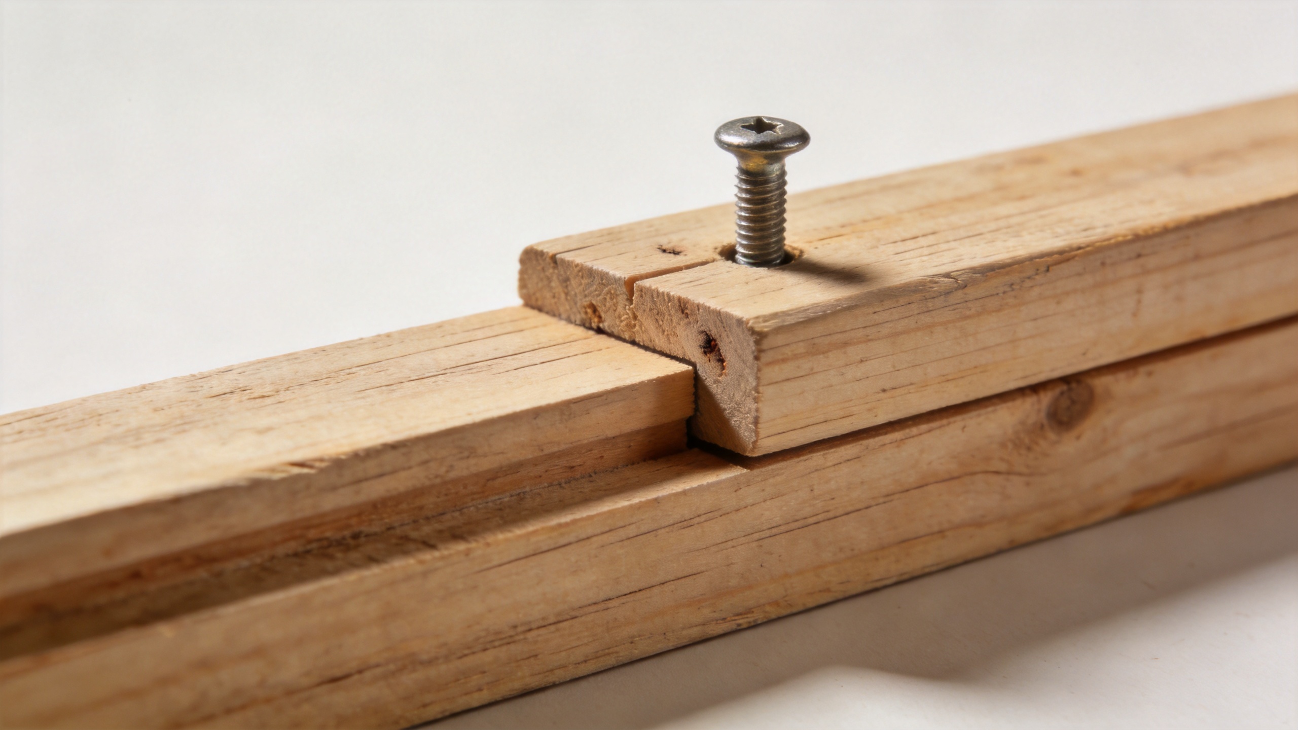
Shank bending, shear, or fracture
A bent or fractured screw points toward lateral action, combined loading, poor alignment, or an abrupt load event. Check whether the joint has slipped enough to put the fastener into an unintended bending condition. Examine the fracture surface, the member faces, and any gap that lets the assembly rack. Do not assume a higher-strength screw is the answer: a stiffer or stronger fastener can transfer stress into the timber, plate, or adjacent connection unless the full detail is checked.
Timber splitting and group effects
Splits parallel to grain, cracks at ends, or several distressed fasteners often indicate a layout or installation issue. A screw placed too near an edge or end can wedge the timber; dense timber, dry timber, omitted pilot holes where required, or aggressive driving can make that worse. Check spacing, edge distance, end distance, penetration, and installation angle against the applicable design and product documentation. Inspect every screw in the group, not only the one that first drew attention.
Check whether the installed fastener is appropriate
Names can mislead a repair decision. A machine screw is generally intended for a tapped hole or nut and is not automatically a structural timber connector. A common wood screw may suit light-duty timberwork but may lack the approved structural data needed for a load-bearing joint. A self tapping screw can describe a thread-forming function, not a verified structural capacity. Likewise, a hex screw head style says little about withdrawal, bending, corrosion resistance, or timber-connection approval.
Confirm the specific screw product against the approved schedule. Review its diameter, threaded length, head geometry, steel grade, corrosion protection, declared performance, and installation method. Outdoor or wet-service exposure deserves particular attention: rust at the head, red staining in the wood, coating loss, or pitting can reduce section and signal a moisture-management problem. The repair must address both the degraded screw and the source of the exposure.
Use a disciplined on-site inspection sequence
- Stabilize and document. Restrict loading as directed by the project safety process; photograph the connection before changing it.
- Map movement. Identify which member moved and whether the dominant action is withdrawal, shear, rotation, or a combination.
- Inspect timber condition. Check for splits, crushing, decay, moisture staining, and local damage around each screw.
- Verify the fastener. Compare the installed screw and layout with drawings, product documentation, and installation instructions.
- Check the load path. Ask what changed: construction sequencing, added equipment, snow or wind action, shrinkage, impact, or differential movement.
- Escalate calculations. Have a qualified engineer assess residual capacity and specify the repair detail before the connection returns to service.
Common diagnostic mistakes to avoid
Adding another screw beside the failed one is a common quick fix. That can be unsuitable if the original layout already lacks edge distance, if the timber has split, or if the load path is wrong. Another mistake is judging a fastener only by diameter. Thread geometry, penetration, head bearing, grain orientation, spacing, service class, and installation angle all influence the connection.
After years of fastener selection work, a recurring lesson is that many assembly failures trace back to mismatched specification or installation rather than a simple product defect. In a load-bearing timber connection, the useful question is not “Which screw is stronger?” but “Which verified repair detail restores the required load path in this actual timber condition?”
Turn the diagnosis into a controlled repair plan
A complete repair plan should state the observed failure mode, the condition of the timber, the approved replacement screw or alternate connector, pilot-hole and installation requirements, spacing and edge/end distances, corrosion protection, and inspection hold points. If several locations are affected, expand the survey beyond the first failed connection. Suppliers can support traceability records, dimensional inspection, standards documentation, and technical clarification, but the final structural decision belongs with the project’s qualified design authority.
Careful diagnosis keeps a single failed screw from becoming a repeated connection problem. Document the evidence, identify the governing mode, verify the fastener and timber condition, and have the repair checked against the applicable design requirements before the joint carries service load again.