EN

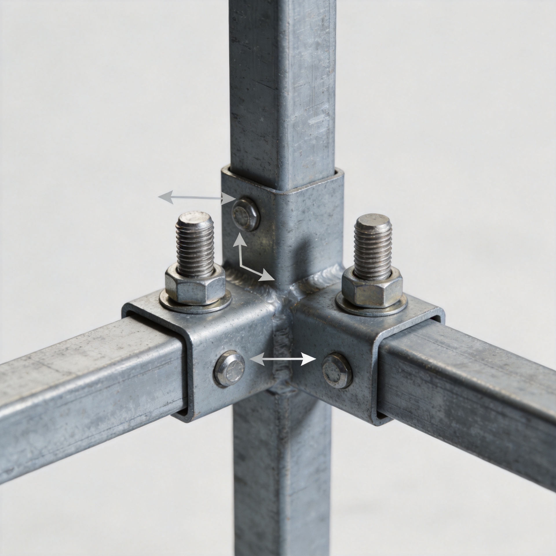
Why Fasteners Bend Under Shear Loading in Steel Frame Structures
A fastener in a steel frame is often described as “in shear,” yet field inspections sometimes reveal a visibly curved shank, elongated hole, tilted washer, or a bolt that no longer sits squarely against the connected plates. That condition deserves more than a quick decision to use a stronger fastener or a different fastener grade. Bending usually means the connection has developed a lever arm, rotation, or uneven bearing condition that was not part of the intended load path.
As a fastener selection engineer, I start with the joint rather than the hardware alone: where the force enters, how the plates bear, whether the plies stay in contact, and whether installation has left clearance or misalignment around each fastener. A threaded fastener can have adequate nominal shear capacity and still bend when the connection geometry turns sideways movement into a local moment. The useful question is not simply “did the fastener fail?” but “what caused the joint to ask it to resist bending?”
Shear does not automatically mean a purely sideways load
In an ideal bearing-type joint, plates try to slide relative to one another and the fastener shank transfers that load across a defined shear plane. The fastener remains supported by the hole walls, the connected material stays seated, and the force is shared as the design assumes for each fastener location. Real steel-frame joints are less tidy. Small gaps, oversized or damaged holes, plate flexibility, eccentric brackets, and uneven contact can shift the line of force from the shank centerline.
Once that offset exists, the fastener sees a bending moment in addition to shear. Rotation can also introduce tension. This is why a mechanical fastener that looks bent may be reporting a connection-level problem rather than merely a low material strength. It is also why replacing it with a larger part without checking the joint can leave the original mechanism in place.
Common mechanisms that make a fastener bend
1. Clearance lets the joint pick up load abruptly
Standard holes need some installation clearance, but excessive clearance changes how a joint engages. A plate can move before its hole bears fully on the shank. The first contact may occur at one edge, creating concentrated bearing and a short lever arm. As movement continues, the shank may be forced to rotate rather than transfer a uniform transverse load. Look for polished contact arcs, oval holes, or one-sided witness marks; they often show where the load first arrived.
2. Thin or flexible plates rotate around the connection
A fastener can be straight when installed and bend later because the connected plates flex. If one plate curls, separates, or rotates under service load, the grip region loses continuous support. The shank then spans a small gap like a short beam. The issue becomes more likely near thin tabs, single-angle details, flexible end plates, or brackets whose load is applied at an offset from the supporting steel.
This is an important distinction: increasing the strength grade does not automatically remove the bending demand. The connection may still rotate. A sound review considers plate thickness, edge distance, washer bearing, contact between plies, and the stiffness of the part delivering the load.
3. Eccentricity creates a lever arm
Steel-frame details often include clips, seats, offsets, and attachments that place the applied force some distance from the fastener group. That distance creates a moment. If the group layout, plate stiffness, or load distribution does not account for it, one fastener can take more shear and more bending than its neighbors. A bent fastener near the outer row of a group is a clue to compare deformation across the entire group, not just at the damaged location.
4. Bearing deformation changes the load path
Bearing is the compressive contact between a fastener and the wall of its hole. In steel connections, bearing deformation, tear-out near an edge, and fastener shear are different limit states. When bearing deformation develops, the hole can elongate and the contact point can shift. The shank is no longer loaded where the original geometry assumed, which can increase rotation and local bending. A stainless fastener may be appropriate for corrosion exposure, but corrosion resistance does not solve an unfavorable bearing detail or a softened connection plate.
5. Installation errors leave the joint unsupported
Misaligned holes, incomplete seating, wrong washer placement, mixed component dimensions, or uneven tightening can leave a gap that only becomes obvious after the structure is loaded. A threaded fastener that clamps across paint buildup, burrs, distorted surfaces, or an unintended spacer may be carrying the joint through a narrow contact zone. During inspection, check the installed stack-up, not only the fastener shank. A straight replacement installed through the same unsupported gap can develop the same deformation pattern.
What a field inspection should establish
Do not assume a bent fastener is an isolated maintenance item. Start by securing the area and following the project’s engineering and safety procedures. Then document the condition before disassembly: fastener location, orientation of bend, hole shape, plate separation, washer imprint, coating damage, and whether nearby fasteners share the same symptoms. A consistent bend direction can reveal a connection rotation pattern or an applied load that is not centered.
- Compare hole diameters and edge regions with the approved detail; look for ovality, local crushing, or cracks.
- Check whether the connected plies are fully bearing or whether a gap opens under load.
- Review the force direction and any offset bracket, hanger, or secondary attachment.
- Verify the specified fastener diameter, grip length, washer arrangement, and installation sequence.
- Assess corrosion, loss of section, or coating damage separately from the geometric problem.
- Have the responsible structural engineer evaluate any member distortion, repeated movement, or evidence of combined shear and tension.
Do not infer a safe capacity from appearance alone. Site conditions, material grades, hole type, fastener pretension requirements, and governing design rules all matter. The inspection should feed a project-specific connection check rather than a generic hardware substitution.
How to reduce bending demand in the next detail
Effective corrections address the load path. First, place the fastener group so the applied force is as direct and symmetric as the detail allows. Then provide adequate plate stiffness and contact so every fastener shank is supported rather than bridging a separating gap. Hole size, edge distance, spacing, and the number and arrangement of fasteners should be checked against the applicable project standard by the connection designer.
Where movement, vibration, or repeated loading is expected, verify that the selected fastening approach matches the service condition. A custom fastener may be useful when a standard part cannot achieve the required grip, geometry, coating, or material combination, but it should follow an engineered specification—not compensate for an unresolved eccentric load path. If corrosion conditions require a stainless fastener, review galvanic compatibility, strength class, and the rest of the joint system at the same time.
A practical sequence is simple: identify the actual load direction, locate every offset, confirm plate contact and stiffness, check the designed limit states, and only then select or replace the fastener. That order is more reliable than choosing the highest-strength option first.
The takeaway
Fasteners bend under shear loading when a steel-frame joint stops behaving like a simple, well-supported shear connection. Clearance, plate rotation, eccentricity, hole bearing damage, and installation gaps can each convert lateral force into combined shear, bending, and sometimes tension. Treat the visible bend as evidence about the joint’s force path. A careful connection review, backed by the project engineer’s calculations and inspection criteria, is the right basis for a durable repair.