EN

Why Self Tapping Screws Fail in Hard Plastic and What to Try Instead
A screw can look secure at the end of assembly and still become the weak point of a hard-plastic enclosure. The usual pattern is familiar: the first build feels fine, then a boss splits, threads strip during service, or clamp load fades after a few reassemblies. The problem is not that every self tapping screw is unsuitable. It is that the screw, pilot hole, boss geometry, resin grade, and installation torque have to work as one system.
From an electronics-assembly perspective, installation convenience is important, but it cannot replace a controlled fastening design. A hard plastic has less ability to flow around a thread than a softer resin. When the screw displaces too much material, the boss experiences radial load and hoop stress. If the wall is thin, the base has a tight radius, or the driver torque is high, cracking can follow. If the hole is too large, the same screw may turn easily but leave too little thread engagement to retain clamp load.
What actually causes a self tapping screw to fail in hard plastic?
“Self tapping” describes how the screw forms or cuts its mating thread; it does not identify a universal plastic-fastening solution. Hard, glass-filled, aged, cold, or otherwise brittle plastics offer a narrower assembly window than ductile materials. A design that survives a hand-built sample may behave differently at production speed or after repeated service.
1. The pilot hole is undersized
An undersized pilot hole forces the screw to displace more plastic. In a hard material, that raises insertion torque and outward pressure in the boss. The immediate symptoms can be a stalled driver, a damaged recess, a snapped screw, or whitening around the hole. The less obvious outcome is a small crack that grows when the assembly sees vibration, temperature cycling, or later removal.
A useful preliminary check is to compare the pilot-hole diameter with the thread’s minor and major diameters, then validate it with the actual resin and fastener. Search guidance commonly places a hard-plastic starting hole toward roughly 80–85% of the screw’s outer diameter, but that is not a release specification. Thread geometry, filled versus unfilled resin, boss diameter, and required pull-out load can shift the acceptable dimension.
2. The boss cannot carry the hoop stress
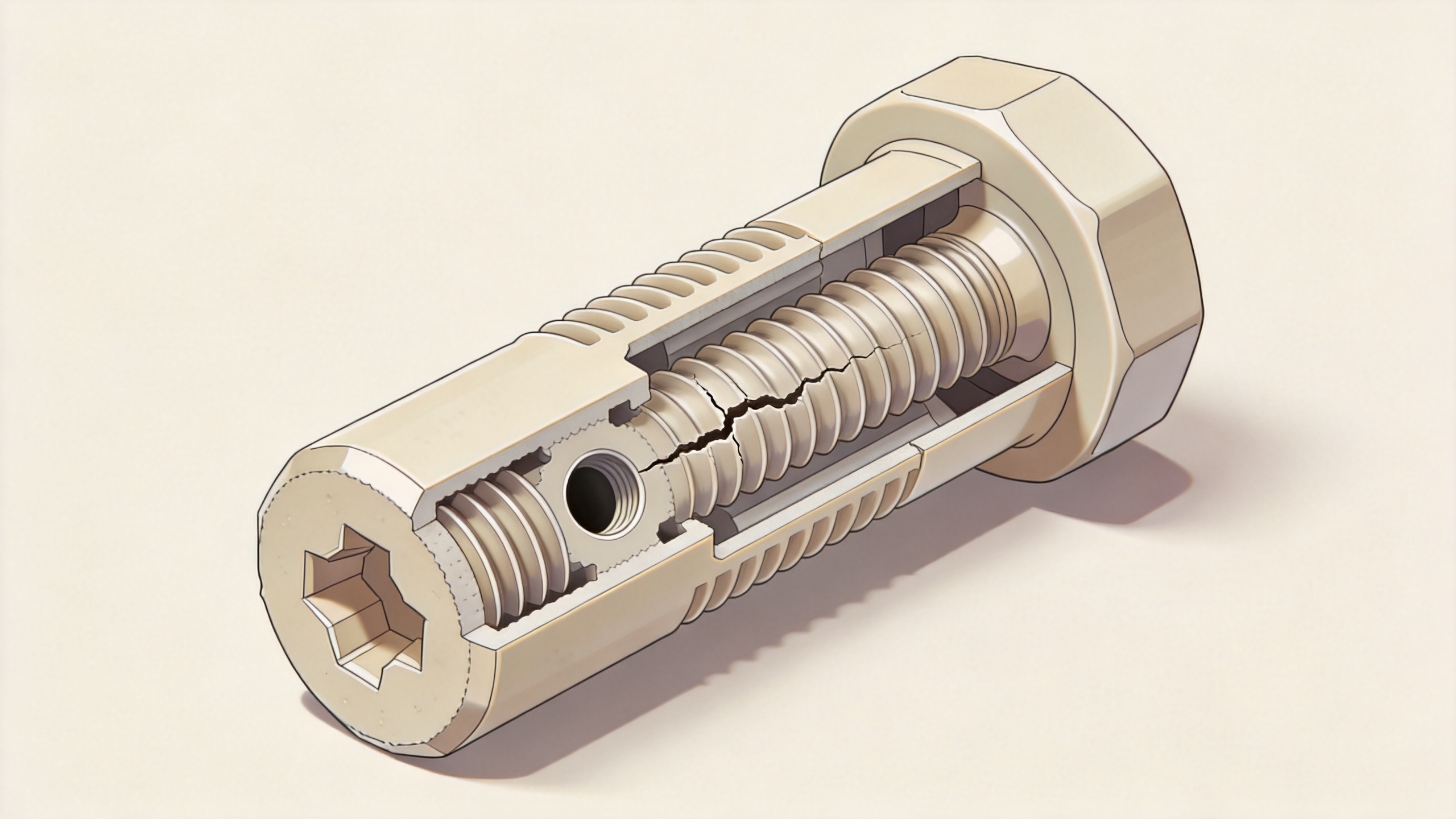
Even the right pilot hole cannot rescue a very thin or poorly supported boss. As the screw forms a thread, it presses outward on the surrounding plastic. A thin wall, an abrupt boss base, or a boss too close to an exterior surface concentrates that load. The result may be a visible split, a radial crack hidden under the head, or stripped threads after the plastic relaxes.
Before changing the fastener, inspect the whole feature: outside diameter, wall thickness, base radius, supporting ribs, engagement length, and clearance from nearby openings. Many teams move from choosing a low-unit-cost screw to reviewing the mating system, which is usually the more useful shift. A modest geometry change can matter more than a stronger driver setting.
3. Torque is treated as a feel rather than a process setting
Hard plastic makes the assembly window small. Too little torque can leave a loose joint; too much torque can distort the thread, crack the boss, or overload the head. A clutch-controlled driver and a torque study on production-equivalent parts give more reliable information than a technician’s hand feel. Record both insertion torque and final seating torque, especially when the same screw will be removed during maintenance.
4. The joint must be serviced more often than the thread can tolerate
A self tapping screw creates its own mating thread on the first pass. Reinstalling the screw can work when the original thread is carefully re-engaged, but repeated removal raises the chance of cross-threading or material loss. For a disposable cover, that trade-off may be acceptable. For a service door, control box, or product expected to be opened many times, it is often not.
Check the failure before selecting another screw
The failed part usually tells you which variable changed. Use this short diagnostic sequence:
- Look at the boss. A split wall points toward hoop stress, weak geometry, or excessive torque.
- Inspect the plastic thread. Powdered or flattened material suggests insufficient engagement, repeated cycling, or an unsuitable thread form.
- Measure the pilot hole. Compare actual molded or drilled size with the drawing and with the fastener supplier’s recommendation.
- Review the driver record. Check bit wear, speed, torque setting, seating depth, and operator variation.
- Confirm the resin condition. Grade, filler content, moisture history, molding quality, and operating temperature all affect how a screw behaves.
This order matters. Replacing one self tapping screw with another without measuring the boss and process can hide the cause for one build and reproduce it in the next.
What to try instead
Use a thread-forming screw designed for plastic
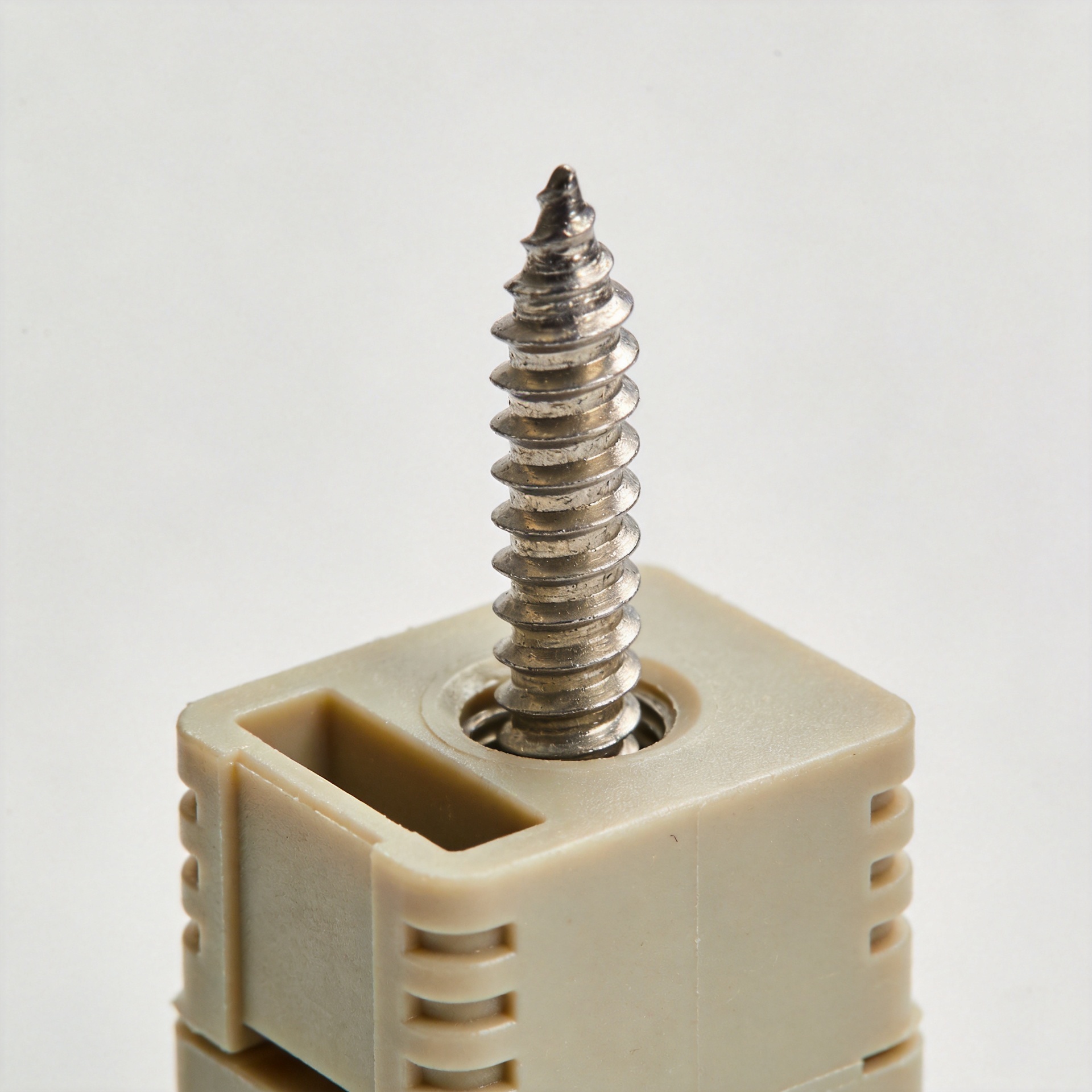
A purpose-designed plastic thread-forming screw is often the first alternative when the joint is assembled once or only occasionally. Its thread profile can reduce material stress compared with a generic cutting-thread fastener while retaining useful pull-out performance. This is a design-and-test choice, not an automatic upgrade: choose the diameter, pilot hole, engagement length, boss dimensions, and driver torque together. A wood screw is generally a poor substitute because its aggressive thread and taper were developed for a different substrate and can overload a hard-plastic boss.
Use a machine screw with an insert for repeated service
If the enclosure will be opened repeatedly, a machine screw paired with a molded-in, heat-set, press-fit, or ultrasonic insert may provide a more stable service thread. The insert moves thread load out of plastic that would otherwise be cut directly, while the machine screw can be replaced without reforming the boss. Insert choice must match resin, wall thickness, installation method, and thermal exposure; a rushed insert operation can create its own cracking or positional issues.
Use through-fastening when access permits
Where both sides of the joint are accessible, a bolt-and-nut arrangement, captive nut, or backed-up machine screw can remove the reliance on a plastic thread altogether. This route adds components and assembly steps, but it is worth considering for high clamp load, frequent servicing, or safety-critical retention. A hex screw can be useful where tool access and controlled tightening are practical, but the head style alone does not solve a weak boss.
Change the joint, not only the screw
Sometimes the reliable alternative is a locating feature, snap fit, latch, adhesive, or a combination of features that reduces the load carried by the screw. For example, use dowels or shoulders to take shear load and let the fastener supply clamp force. That distinction can lower stress on the plastic thread and make torque variation less consequential.
A practical selection path
| Joint condition | Reasonable starting option | What to validate |
|---|---|---|
| One-time assembly, moderate load | Plastic-specific thread-forming screw | Pilot hole, boss wall, insertion torque, pull-out |
| Hard or brittle plastic | Optimized thread-forming screw plus reinforced boss | Crack resistance, torque window, temperature effects |
| Repeated disassembly | Machine screw and insert | Insert retention, alignment, service torque |
| High load or accessible rear face | Through-fastening or captive nut | Clamp load, clearance, assembly access |
Prototype the complete joint with production-equivalent resin and the intended driver. Then test first assembly, retightening, removal and reinstallation, temperature exposure, and vibration appropriate to the application. If your priority is fast assembly, a self tapping screw may remain appropriate; if your priority is repeatable service life, the insert-based machine-screw route often deserves comparison first.
Bottom line
A self tapping screw fails in hard plastic when the fastening system asks brittle material to absorb more radial stress, torque, or service cycling than its geometry can support. Start with the actual failure mode, measure the pilot hole and boss, and validate torque on representative parts. Then choose between a plastic-specific screw, a machine screw with an insert, or through-fastening based on the required load and service life. That approach gives you a defensible joint design instead of a last-minute fastener swap.